7805 voltage regulator circuit is one variant of the three terminal Positive Voltage Regulator. IC 7805 operated at maximum load current at a positive fixed voltage 5V 1A, but work on the maximum current will increase the thermal level. Aluminium heatsink is needed to reduce the level of heat, though internally IC 7805 has a thermal over-load protection.
The DC voltage regulator that works at the maximum rate is an unfavorable condition. Besides the heat level increases, it will likely be fatal if an increase in the load current due to short circuit. A good idea is to increase load current capability by adding an external transistor.
Based on the manual of IC 7805 has given a basic circuit to operate the IC at higher load currents. Download 7805 datasheet manual.
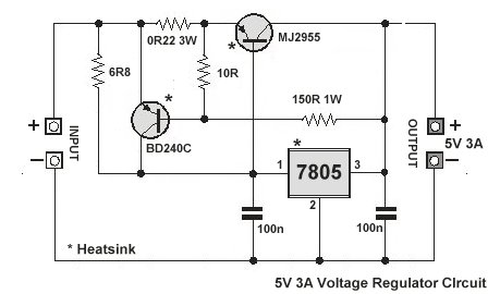
7805 Voltage Regulator Circuit - Increase Current
In the following circuit to increase 7805 output current up to 3 amperes, must be added a complementary NPN transistor MJ2955. The advantage of this technique is to overcome when there is short-circuit as described above. When there is a voltage drop, then the circuit will reduce the maximum current consumption. So the problem can be solved.
Transistor BD240C in the DC voltage regulator circuit serves as a current limiting. The transistor is open when the voltage at 10R+0.22R be higher than 0.6-0.7 Volts, which leads to a reduction to zero of the T2 base current. The voltage at which the short-circuit protection starts to act, is given by voltage sum on 0.22R and 10R. Base voltage is determined by resistors 10R and 150R. In this circuit did not happen over-thermal when short-circuit occured, the maximum current was only 0.5 Ampere.
Hope this simple explanation may help in making a higher current-voltage regulator using IC 7805. You can open the manual datasheet of the 7805 voltage regulator circuit for more information.Click here for High Current 7812 Voltage Regulator Circuit.
